Outdated Drivers Are Slowing You Down
Windows Errors? Fix Them Before They Spread
Repair common Windows errors and clear accumulated junk for a smoother, more stable PC - no reinstall needed.Free scan · no reinstallCrashes, No Sound, or Screen Glitches?
Random freezes, missing sound and display glitches usually trace back to one bad driver. Find and replace yours safely.Free scan · under a minuteOne free scan finds every outdated or missing driver and matches the right update for your exact hardware.
Scan My Drivers Free →Free scan · exact hardware match
ThatPainter is reader-supported. When you buy through links on our site, we may earn an affiliate commission. Learn More
Computer-aided design (CAD) is software used to create, modify, analyze, document, and communicate two-dimensional drawings and three-dimensional models. CAD can describe anything from a floor plan or laser-cut profile to a mechanical assembly, building model, electronic layout, or manufactured product.
The Tool Desk
Outbyte Driver Updater FREEFix the driver behind crashes, sound loss and screen glitchesFind Drivers →Outbyte PC Repair FREEClear out junk files and repair common Windows errorsFree Scan →#1 Best Overall
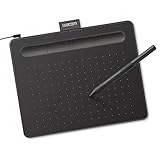
- Wacom Intuos Small Graphics Drawing Tablet: Enjoy industry leading tablet performance in superior control and precision with Wacom's EMR, battery free technology that feels like pen on paper
- Works With All Software: Wacom Intuos tablet can be used in any software program to explore new facets of digital creativity; draw, paint, edit photos/videos, create designs, and mark up documents
- What the Professionals Use: Wacom's industry leading pen technology and pen to paper feeling makes it the preferred drawing tablet of professional graphic designers
- Software and Training Included: Only Wacom gives you software with every purchase. Register your Intuos tablet and gain access to some of the best creative software and Wacom's online training
- Wacom is the Global Leader in Drawing Tablet and Displays: For over 40 years in pen display and tablet market, you can trust that Wacom to help you bring your vision, ideas and creativity to life
CAD is more than digital drawing: modern systems may include parametric modeling, assemblies, rendering, simulation connections, manufacturing preparation, collaboration, and revision control. However, a CAD model does not automatically prove that a design is safe, manufacturable, code-compliant, or economical.
What does CAD stand for?
CAD stands for computer-aided design. “Computer-aided” means that software assists with geometry, dimensions, constraints, documentation, and revisions; it does not replace the designer’s decisions or engineering judgment.
CAD may be used to:
- Draft and annotate 2D drawings.
- Create 3D wireframe, surface, solid, mesh, or freeform models.
- Define relationships, dimensions, tolerances, materials, and configurations.
- Check fit, clearances, mass properties, and interference.
- Produce technical drawings, bills of materials, and manufacturing documentation.
- Prepare data for simulation, CNC machining, 3D printing, construction, or inspection.
- Manage revisions, approvals, permissions, and design information.
Siemens defines CAD as software for creating, modifying, analyzing, and documenting 2D or 3D graphical representations. Its overview of CAD also distinguishes history-based and direct modeling approaches.
How does CAD work?
CAD workflows vary by industry and software. A designer exploring a concept may work nonlinearly, while an engineer preparing a production part may follow a carefully controlled sequence.
- Define requirements. Establish dimensions, interfaces, materials, loads, manufacturing methods, tolerances, costs, regulations, and performance targets.
- Create a sketch or layout. Draw profiles, reference geometry, dimensions, and constraints. In 2D CAD, this may be the main design; in 3D CAD, it is often the starting point for a feature.
- Build the model. Use lines and arcs, solid features, surfaces, meshes, freeform tools, or a combination of methods.
- Add design intent. Apply parameters, relationships, constraints, materials, configurations, metadata, and tolerances so the model can be changed predictably.
- Review and validate. Check dimensions, clearances, mass properties, fit, manufacturability, and—where appropriate—simulation results.
- Create documentation. Generate drawings, sections, annotations, exploded views, bills of materials, inspection references, or model-based definitions.
- Prepare downstream outputs. Export files, generate CAM toolpaths, send a model to a 3D printer, create sheet-metal flat patterns, or coordinate the design with construction and data-management systems.
- Manage revisions. Track versions, approvals, changes, released files, and the relationship between design data and production data.
The workflow is iterative. A manufacturing constraint may require a design change, a simulation result may prompt a geometry revision, and a supplier may request a different file format.
The main types of CAD
2D CAD
2D CAD creates planar drawings from lines, arcs, circles, polylines, dimensions, hatches, symbols, and annotations.
Typical uses: floor plans, elevations, schematics, manufacturing drawings, site layouts, legacy drafting, laser-cutting profiles, and CNC profiles.
2D CAD is often fast and familiar, and formats such as DWG and DXF are widely exchanged. Its limitations become clearer when a project requires a complete 3D object, automated view coordination, interference checking, or reliable mass-property calculations. Multiple views may need to be updated manually unless the software links them to a 3D model.
Recommended Free Tools
3D wireframe modeling
Wireframe models represent an object with points, lines, and curves without necessarily defining filled surfaces or an enclosed volume. They are useful for conceptual layouts, spatial reference geometry, frameworks, and early design studies.
A wireframe does not automatically provide a valid volume, mass, material definition, or manufacturable object. It can also be difficult to interpret when many lines overlap.
Surface modeling
Surface modeling defines the exterior skin of an object without necessarily describing a solid interior. It is common in automotive bodywork, consumer-product housings, aircraft and marine forms, industrial design, and smooth freeform shapes.
A surface model may not be watertight or contain valid volume and mass properties. Additional trimming, stitching, thickening, or conversion may be required before it can support manufacturing or engineering calculations.
Rank #2

- Word-first 16K Pressure Levels: The upgraded stylus features 16,384 levels of pressure sensitivity and supports up to 60 degrees of tilt, delivering smoother lines and shading for a natural drawing experience. With no battery or charging needed, it operates like a real pen, making it easy for beginners to create effortlessly. This functionality helps novice artists develop their skills and explore their creativity without the intimidation of complex tools
- Designed for Beginners: This drawing pad desinged with 8 customizable shortcuts for both right and left-hand users, express keys create a highly ergonomic and convenient work platform
- Perfectly Adapted for Android: The XPPen Deco 01 V3 art tablet supports connections with Android devices running version 10.0 and above. It is recommended to download the XPPen Tools Android application, which adapts to your smartphone's screen aspect ratio, ensuring accurate mapping. It also supports mapping on Android screens with different aspect ratios in portrait mode
- Large Drawing Space, Bigger Bold Inspiration: This expansive drawing pad has10 x 6.25-inch helps you break through the limit between shortcut keys and drawing area
- Easy Connectivity for Beginners: The Deco 01 V3 offers USB-C to USB-C connectivity, plus adapters for USB C. This ensures easy connection to various devices, allowing beginner artists to set up quickly and focus on their creativity without compatibility concerns. Whether using a laptop, tablet, or desktop, the Deco 01 V3 provides a seamless experience, making it an ideal choice for those just starting their digital art journey
Solid modeling
Solid modeling represents a closed, volumetric object. It is well suited to mechanical parts, assemblies, mass and center-of-gravity calculations, interference checking, manufacturing documentation, CNC preparation, and many 3D-printing workflows.
SOLIDWORKS documentation distinguishes 2D drawings, wireframe models, surface models, and solid models, and explains how 2D drawings can be generated from 3D solids.
Parametric or history-based CAD
Parametric CAD controls geometry through dimensions, constraints, relationships, and an ordered sequence of features. If an upstream parameter changes, dependent geometry can update automatically.
This approach is valuable when a product has controlled design intent, repeated revisions, or families of related parts. A well-structured model can make changes efficient and predictable.
Free tools Windows power users keep installed
One-click scans. No signup required.
The trade-off is fragility. A change to an early sketch may break later features, an underconstrained sketch may behave unpredictably, and imported geometry may contain little or no useful feature history. Stable references, sensible feature order, and intentional constraints matter.
Direct or explicit modeling
Direct modeling edits selected geometry by pushing, pulling, moving, offsetting, or reshaping it without depending on a conventional feature-history tree.
It is often effective for imported models, irregular geometry, and rapid concept changes. It can be easier to explore than a heavily constrained parametric model. The trade-off is that design intent may be less explicit, and repeated parameter-driven changes may require more manual work.
Mesh and facet-based modeling
Mesh modeling represents geometry with polygons or facets rather than traditional parametric solids and surfaces. It is common for 3D scanning, sculpting, organic forms, visualization, reverse engineering, and 3D printing.
Do these 3 things before closing this tab:
1Scan for outdated or missing drivers - takes under a minute2Clear out junk files and repair common Windows errors3Fix the driver behind crashes, sound loss and screen glitchesA mesh is not automatically equivalent to a dimensionally controlled solid. It may need cleanup, conversion, inspection, or remodeling before it is suitable for engineering changes or production documentation. Siemens’ current Designcenter CAD material lists facet-based, explicit solid and surface, parametric, and direct modeling.
CAD modeling methods compared
| Method | What it represents | Best suited to | Main caution |
|---|---|---|---|
| 2D drafting | Planar lines, symbols, dimensions, and annotations | Documentation, plans, schematics, profiles | Does not inherently define a complete 3D object |
| Wireframe | Points, lines, and curves | Layouts and spatial reference | No guaranteed surface or volume |
| Surface | Exterior skins | Organic forms and industrial styling | May not be watertight or volumetric |
| Solid | Closed volumetric objects | Mechanical parts, assemblies, manufacturing | Still requires design and manufacturing validation |
| Parametric | Geometry plus relationships and feature history | Controlled revisions and product families | Feature trees can become fragile |
| Direct | Explicit geometry edits | Concepts and imported or irregular models | Design intent may be less structured |
| Mesh | Polygonal or faceted surfaces | Scanning, sculpting, printing, visualization | Usually lacks parametric design intent |
Mechanical CAD, architectural CAD, civil CAD, and ECAD
Mechanical CAD (MCAD)
MCAD is used for parts, assemblies, mechanisms, machines, tooling, sheet metal, plastics, fixtures, frames, and manufactured products. Common capabilities include parametric solids, assembly relationships, sheet-metal tools, weldments, drawings, tolerancing, motion analysis connections, and manufacturing handoff.
Architecture, construction, and BIM
Architectural CAD supports plans, sections, elevations, details, layouts, and visualization. BIM—building information modeling—is broader than drawing building geometry. A BIM workflow coordinates building elements, relationships, schedules, quantities, and project information.
A simple 2D floor plan is CAD. An information-rich, coordinated building model is a BIM workflow. The terms should not be treated as interchangeable.
Recommended Free Tools
Rank #3

- Customize Your Workflow: The 6 customizable press keys on Huion H640P drawing tablet for pc let you assign your most-used commands—like undo, zoom, brush switch, or save—so you can keep your hands on the tablet and your mind on the art. Whether you're a digital painter switching brushes, or a comic artist zooming in and out, these keys keep your workflow smooth and uninterrupted. Plus, the Huion driver lets you save different shortcut profiles for different apps, so you never have to reconfigure when switching software.
- Professional Pen Performance: Huion H640P drawing pad for computer comes with the battery-free PW100 stylus that's always ready when inspiration strikes. With 8192 levels of pressure sensitivity, every light sketch, or bold stroke responds naturally to your hand—just like a real pen. The 5080 LPI resolution and 233 PPS report rate deliver lag-free, precise strokes, so you can draw confidently without second-guessing your cursor. The pen side buttons help you switch between pen and eraser instantly.
- Compact and Portable: Huion H640P computer graphics tablet features a compact, ultra-portable design at just 0.3 inches thin and 0.61 lbs light, so it slides easily into your backpack—perfect for sketching in coffee shops, taking notes in class, or editing on the go between home and studio. The 6x4 inch active area offers enough room for natural pen movements while fitting comfortably on crowded desks, or lecture hall seats.
- Stable Compatibility: Huion H640P graphic drawing tablet works seamlessly with Mac, Windows, Linux PCs, and Android smartphones/tablets (OS version 6.0 or later). Left-handed friendly, and you just need to flip the tablet and adjust the settings in the driver. Please note: H640P does NOT support iPhone/iPad.
- Move Beyond the Mouse: Huion Inspiroy H640P is a pen tablet that replaces your mouse for more natural, precise control. Freehand draw, take notes, or even play OSU—everything you do with a mouse, you can do better with a pen. The precise tip makes it ideal for detailed photo editing, graphic design, or signing PDF. Meanwhile, the ergonomic pen grip helps you avoid the strain that comes from hours of using a mouse.
Civil and infrastructure design
Civil design tools handle survey data, terrain, grading, roads and corridors, alignments, drainage, utility networks, site layouts, and infrastructure documentation.
Electronic and electrical CAD (ECAD)
ECAD supports schematics, PCB layouts, wiring, harnesses, component libraries, connectivity, and electrical design rules. ECAD and MCAD often exchange enclosure geometry, boards, connectors, mounting points, and clearance information.
Industrial and artistic 3D modeling
CAD-adjacent tools may focus on organic form development, rendering, animation, jewelry, furniture, or digital fabrication. They can create precise or visually sophisticated forms without offering the same constraints, tolerances, assemblies, documentation, or manufacturing controls as engineering-focused CAD.
What is CAD used for?
Product design and engineering
CAD is used for consumer products, appliances, tools, enclosures, automotive components, industrial machinery, medical devices, and aerospace parts. Designers can explore proportions and surfaces, while engineers can define interfaces, tolerances, materials, assemblies, and production drawings.
What’s actually slowing this PC down?
Pick the symptom - the matching free tool is one click away.
Manufacturing
Manufacturers use CAD for production drawings, mold and die design, sheet-metal flat patterns, assembly instructions, inspection references, CNC preparation, and 3D-printing files. CAD describes the design; manufacturing operations are normally created in CAM.
Architecture and construction
CAD supports plans, sections, elevations, details, layouts, visualization, and documentation. When connected to BIM tools, model elements can also support coordination, schedules, quantities, and project information.
Civil engineering
Civil CAD supports site design, grading, terrain models, road alignments, drainage, utility networks, survey information, and infrastructure documentation.
Electronics and electrical systems
ECAD tools produce schematics, PCB layouts, wiring diagrams, harnesses, and component data. Mechanical CAD can then be used to check board fit, enclosure clearances, connectors, and mounting features.
The Tool Desk
Outbyte Driver Updater FREEScan for outdated or missing drivers - takes under a minuteDriver Scan →Outbyte PC Repair FREEClear out junk files and repair common Windows errorsFree Scan →Simulation and validation
CAD geometry can be transferred to CAE software for structural stress, thermal behavior, fluid flow, motion, vibration, electromagnetic analysis, and optimization.
CAD geometry is only an input to simulation. Results depend on appropriate materials, loads, boundary conditions, contacts, mesh quality, solver settings, safety factors, and validation against testing or trusted reference data. A colored simulation plot is not proof that a design will work.
Reverse engineering and inspection
CAD models can be reconstructed from 3D scans, point clouds, existing drawings, physical measurements, or imported files. The result may be a reference approximation rather than the original design intent, especially when the source is a mesh or damaged physical object.
CAD versus CAM, CAE, BIM, PDM, PLM, and related technologies
| Technology | Main purpose | Typical output |
|---|---|---|
| CAD | Create and document design geometry | Drawings, 3D models, assemblies |
| CAM | Plan and control manufacturing | Toolpaths, machine code, setup data |
| CAE | Analyze engineering behavior | Stress, thermal, motion, fluid, or optimization results |
| BIM | Coordinate building and infrastructure information | Information-rich building or civil models |
| PDM | Manage engineering files and revisions | Controlled files, approvals, revision history |
| PLM | Manage product information across its lifecycle | Product records, workflows, and change processes |
| ECAD | Design electrical and electronic systems | Schematics, PCB layouts, harness data |
| 3D scanning | Capture physical geometry | Point clouds or meshes |
Some platforms combine several functions. For example, Autodesk Fusion presents CAD, CAM, CAE, PCB, data management, and collaboration capabilities in one integrated environment. That packaging does not eliminate the conceptual differences: CAD describes the design, CAE analyzes behavior, and CAM defines manufacturing operations.
Quick wins for a faster PC:
Clear out junk files and repair common Windows errorsFree Scan →Scan for outdated or missing drivers - takes under a minuteDriver Scan →Repair Windows errors before they cause bigger problemsFix Now →Rank #4

- PLEASE NOTE:XPPen Artist13.3 Pro drawing tablet Need to connect with computer,you need to use it with your computer or laptop, the 3 in 1 cable is included
- Drawing Tablet with Screen: Tilt Function- XPPen Artist 13.3 Pro supports up to 60 degrees of tilt function, so now you don't need to adjust the brush direction in the software again and again. Simply tilt to add shading to your creation and enjoy smoother and more natural transitions between lines and strokes
- Graphics Tablets: High Color Gamut- The 13.3 inch fully-laminated FHD Display pairs a superb color accuracy of 88% NTSC (Adobe RGB≧91%,sRGB≧123%) with a 178-degree viewing angle and delivers rich colors, vivid images, and dazzling details in a wider view. Your creative world is now as powerful as it is colorful
- Drawing Pad: One is enough- The sleek Red Dial on the display is expertly designed with creators in mind, its strategic placement allows for natural drawing postures. With just one wheel, you can effortlessly zoom in and out, adjust brush sizes, and flip the canvas—all tailored to suit the habits of everyday artists. The 8 customizable shortcut keys allow you to personalize your setup, streamlining your workflow and enhancing creative efficiency
- Universal Compatibility & Software Support:supports Windows 7 (or later), Mac OS X 10.10 (or later), Chrome OS 88 (or later), and Linux systems. Fully compatible with major creative software including Photoshop, Illustrator, SAI, and Blender 3D. Register your device to access additional programs like ArtRage 5 and openCanvas for expanded creative possibilities.
Benefits of CAD
- Faster iteration: Designers can modify geometry without redrawing every view manually.
- More consistent documentation: Dimensions, annotations, and linked views can reduce manual coordination errors.
- Reuse: Components, templates, libraries, features, and configurations can support recurring work.
- Better visualization: Teams can review a design before committing to tooling or physical prototypes.
- Design-change efficiency: Well-structured parametric models can update related geometry when a key dimension changes.
- Collaboration: Digital models are easier to review, share, mark up, and connect to suppliers or downstream teams.
- Downstream integration: Models can feed simulation, manufacturing, inspection, construction, and product-data workflows.
- Revision records: Managed CAD environments can preserve versions, approvals, and design decisions.
These are potential benefits, not guarantees. Siemens identifies virtual prototyping, design-error detection, reduced rework, and integration with simulation, drawings, manufacturing, and data-management workflows as CAD benefits. The actual result depends on training, modeling discipline, software configuration, and downstream processes.
Limitations and costs of CAD
CAD can reduce repetitive drafting, but it introduces its own costs and risks:
- Software licenses, subscriptions, training, support, and upgrades.
- Hardware, graphics, operating-system, and network requirements for some desktop applications.
- Learning curves and the need for specialist drafting, engineering, manufacturing, or architectural skills.
- Vendor lock-in and dependence on proprietary file formats.
- Translation errors when files move between CAD systems.
- Broken references, unstable topology, or failed parametric rebuilds.
- Slow performance and difficult management of very large assemblies.
- Security, access-control, intellectual-property, export-control, and data-residency concerns.
- False confidence caused by attractive renderings or apparently valid geometry.
A CAD model does not automatically account for material availability, tool access, tolerances and fits, surface finish, assembly sequence, cutting forces, welding distortion, building codes, human factors, supply-chain constraints, or actual product performance. Physical prototypes, inspection, testing, professional review, and regulatory approval may still be necessary.
CAD file formats: native versus neutral
Native formats usually preserve more software-specific intelligence, including feature history, constraints, assemblies, configurations, materials, metadata, and associative references. They may be difficult to open without the original application.
Free tools Windows power users keep installed
One-click scans. No signup required.
Neutral or exchange formats are intended to move geometry between systems, but they do not guarantee that all design intelligence will survive.
| Format | Common role | Important limitation |
|---|---|---|
| STEP | Solid and assembly geometry exchange | May not preserve feature history, sketches, or constraints |
| IGES | Older geometry exchange, especially legacy workflows | Often less convenient than newer exchange approaches |
| STL | Polygon mesh for many 3D-printing workflows | Generally lacks parametric design intent and rich metadata |
| 3MF | Additive-manufacturing-oriented mesh package | Support and preserved data vary by application |
| OBJ | Mesh and appearance-oriented exchange | Not a substitute for a dimensionally controlled solid |
| DXF | Common 2D exchange format | Exact support and retained information vary by product |
| DWG | Widely used drafting format, especially in Autodesk-centered workflows | Compatibility and feature support vary between systems |
| Parasolid, ACIS, JT | Specialist geometry or visualization exchange | Availability and fidelity depend on software support |
Format support varies by product, edition, importer, exporter, and version. Before sending a file to a manufacturer, ask which format and version they require, whether they need a solid or mesh, and whether drawings, tolerances, materials, or assembly data must accompany it. Never assume that conversion is lossless.
Independent reader supportYour contribution helps us test, update, and keep practical guides available for everyone.How to choose CAD software
Choose around the work you need to do rather than the length of a feature list.
- Identify the project type. Is it 2D documentation, a mechanical part, a large assembly, a building, civil infrastructure, an electronic system, or an organic form?
- Choose the modeling approach. Parametric modeling suits controlled revisions; direct modeling suits rapid edits and imported geometry; surface or freeform tools suit complex styling; mesh tools suit scanning and sculpting.
- List required outputs. You may need DWG or DXF drawings, STEP assemblies, STL or 3MF meshes, CNC toolpaths, BIM data, PCB files, or production drawings.
- Match the manufacturing or construction method. CNC machining, injection molding, sheet metal, 3D printing, casting, welding, and construction impose different requirements.
- Consider collaboration. A solo maker, distributed design team, supplier network, and controlled engineering department need different sharing, permissions, and review workflows.
- Check data management. Look for version history, approvals, permissions, auditability, release workflows, backups, and intellectual-property controls.
- Check platform and deployment. Confirm Windows, macOS, browser, mobile-viewer, offline, hybrid, or cloud requirements. “Cloud” does not necessarily mean browser-only.
- Verify licensing. Read commercial-use, privacy, public-document, export, storage, trial, education, and personal-use restrictions.
- Test interoperability. Confirm that customers, suppliers, contractors, and manufacturing partners can exchange the formats you need.
- Evaluate the ecosystem. Training, local expertise, component libraries, integrations, support, and compatible suppliers can matter as much as modeling features.
Examples of CAD software
Autodesk AutoCAD
AutoCAD is commonly associated with general 2D drafting and documentation, with 3D capabilities for suitable workflows. It is a logical category to consider when drawings, layouts, and industry familiarity matter more than advanced mechanical feature modeling.
Do these 3 things before closing this tab:
1Scan for outdated or missing drivers - takes under a minute2Clear out junk files and repair common Windows errors3Fix the driver behind crashes, sound loss and screen glitchesAutodesk Fusion
Autodesk Fusion combines cloud-connected product development capabilities including CAD, CAM, CAE, PCB, data management, and collaboration. It can suit makers, startups, product designers, and small manufacturing teams that want several functions in one environment. Users with strict offline requirements, specialized enterprise workflows, extensive legacy-native compatibility, or highly advanced discipline-specific needs may need another platform or additional tools.
Onshape
Onshape emphasizes browser-delivered CAD, collaboration, version control, and integrated product-data management. It can suit distributed teams that prioritize real-time access and controlled revisions. It may be a poor fit for users who require extensive offline-first operation or a specific desktop-native ecosystem.
SOLIDWORKS Design
SOLIDWORKS Design is aimed at mechanical product development, with parts, assemblies, drawings, and tiered engineering capabilities. It can be a strong fit for traditional mechanical workflows, although cost, device requirements, and ecosystem commitment should be evaluated.
Siemens Solid Edge, NX, and Designcenter
Siemens Designcenter covers a broad range of CAD and product-engineering capabilities, from mainstream mechanical design to advanced multidisciplinary workflows. Siemens Solid Edge and NX occupy different points in that ecosystem. These tools may be more appropriate for organizations needing scalable specialist capabilities than for casual users or beginners.
Best Value
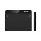
- Battery-Free Pen: StarG640 drawing tablet is the perfect replacement for a traditional mouse! The XPPen advanced Battery-free PN01 stylus does not require charging, allowing for constant uninterrupted Draw and Play, making lines flow quicker and smoother, enhancing overall performance
- Ideal for Online Education: XPPen G640 graphics tablet is designed for digital drawing, painting, sketching, E-signatures, online teaching, remote work, photo editing, it's compatible with Microsoft Office apps like Word, PowerPoint, OneNote, Zoom, Xsplit etc. Works perfect than a mouse, visually present your handwritten notes, signatures precisely
- Compact and Portable: The G640 art tablet is only 2 mm thick, it's as slim as all primary level graphic tablets, allowing you to carry it with you on the go
- Chromebook Supported: XPPen G640 digital drawing tablet is ready to work seamlessly with Chromebook devices now, so you can create information-rich content and collaborate with teachers and classmates on Google Jamboard’s whiteboard; Take notes quickly and conveniently with Google Keep, and effortlessly sketch diagrams with the Google Canvas
- Multipurpose Use: Designed for playing OSU! Game, digital drawing, painting, sketch, sign documents digitally, this writing tablet also compatible with Microsoft Office programs like Word, PowerPoint, OneNote and more. Create mind-maps, draw diagrams or take notes as replacement for mouse
Other specialized categories
Rhino and other surface-oriented tools may suit industrial and organic forms. Creo and CATIA are commonly considered in advanced product-engineering environments. Autodesk Inventor targets mechanical design, while Revit and Civil 3D address architecture/BIM-related and civil-infrastructure workflows. PCB-focused systems serve ECAD requirements. The appropriate choice depends on the project, required file formats, collaboration model, and level of engineering control—not simply on the software’s popularity.
Current pricing examples
The following U.S. pricing signals were checked on August 16, 2026. Prices, taxes, regional availability, plan names, and eligibility can change, so verify the official page before purchasing.
| Product or plan | Observed pricing signal | Important qualification |
|---|---|---|
| Onshape Free | $0 | Non-commercial use; documents are public |
| Onshape Standard | $1,500 per user/year | Paid plan supports private documents and commercial use |
| Onshape Professional | $2,500 per user/year | Paid plan with private documents and additional capabilities |
| Onshape Enterprise | Custom pricing | Contact the vendor |
| SOLIDWORKS Design Standard | $2,820 per user/year | U.S. single-user annual offer; tax excluded |
| SOLIDWORKS Design Professional | $3,456 per user/year | U.S. single-user annual offer; tax excluded |
| SOLIDWORKS Design Premium | $4,716 per user/year | U.S. single-user annual offer; tax excluded |
| Autodesk Fusion | $57/month when billed annually | U.S. pricing signal; trial and limited qualifying personal-use options also advertised |
Official plan details are available from the Onshape pricing page, Onshape plan documentation, the SOLIDWORKS pricing page, and Autodesk’s Fusion extensions and pricing information.
Common CAD mistakes
Using 2D CAD for a 3D assembly problem
2D drawings can document an assembly, but they do not inherently provide robust spatial relationships, interference checking, or mass properties. A 3D assembly workflow is usually more appropriate when fit and movement matter.
Choosing parametric CAD for unconstrained sculpting
Parametric systems are powerful for controlled engineering changes but can feel restrictive during freeform exploration. Direct, surface, or freeform tools may be better for early shape development.
Assuming a STEP import preserves design history
STEP commonly preserves geometry more reliably than feature intent. Imported parts may require rebuilding sketches, constraints, features, parameters, and relationships.
Treating STL as the production master
STL is a mesh exchange format. It may be adequate for printing but is usually a poor master for controlled engineering changes, tolerancing, assemblies, or production drawings.
Overconstraining sketches
Conflicting constraints can make a model fail when edited. Use an intentional constraint scheme and avoid adding relationships that do not support the intended design behavior.
Building fragile feature trees
References to short edges, changing faces, or unstable topology can break after edits. Stable datum geometry, logical feature order, and simpler dependencies make models easier to maintain.
Trusting simulation without checking assumptions
Simulation results are only as meaningful as the material properties, loads, constraints, contacts, mesh, and solver settings behind them. Correlation with testing or trusted data may be necessary.
Confusing a rendering with a manufacturable model
A convincing image can conceal open surfaces, missing wall thickness, impossible tool access, bad tolerances, or unresolved assembly details.
Bottom line
CAD is the digital creation and documentation of design geometry, from 2D drawings to detailed 3D models. The right system depends on what you are designing, how you need to change it, which files you must exchange, how it will be made or built, and whether your work is personal or commercial.
Windows Errors? Fix Them Before They Spread
Repair common Windows errors and clear accumulated junk for a smoother, more stable PC - no reinstall needed.Free scan · no reinstallCrashes, No Sound, or Screen Glitches?
Random freezes, missing sound and display glitches usually trace back to one bad driver. Find and replace yours safely.Free scan · under a minuteFor a reliable choice, start with the workflow—not the brand: define the project, identify the required outputs, choose between parametric, direct, surface, solid, or mesh modeling, check collaboration and data-management needs, and verify licensing and interoperability before committing.
Quick Recap